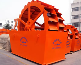
Sand Washer
![]() Home products
Sand making machine
Sand Washer
Home products
Sand making machine
Sand Washer

Sand Washer
- High cleanliness
- Reasonable structure
- High productivity, easy maintenance
- No pollution, long service life
Introduction to Sand Washer
The sand washer is a kind of highly efficient sand washing equipment, combining the advanced techniques and the domestic physical conditions of sand industry. It has the advantages of high cleanliness, reasonable structure and high productivity. During the washing process, little sand runs off. The transmission part separated from the water and sand makes the fault rate further lower than the commonly used sand washers, which makes it the best upgraded equipment in the sand washing industry.
.jpg)
Working Principle of Sand Washing Machine
When the sand washing machine works, the motor drives the impellers slowly after the v-belts, deceleration machine and gears slow down. The sandstone gets into the washing trough through the feeding trough and rotates and then will be ground driven by the impellers. The impurities on the surface and the water vapor coated layer enveloping the sandstone will be removed for dehydration; and when added water, it will form a strong water flow. The impurities and the foreign matters of small proportion overflow from the port, achieving cleaning effect. The clean sand will be taken away by the impellers and poured into the discharge chute.
.jpg)
Structure of Sand Washing Plant
The Sand Washer is basically made up of the lifting device, the rotors, the box and the dynamical part.
(1) The lifting device
The motor, the speed reducer, the bevel gear, two pairs of coupling and the screws constitute the lifting device. The lifting device is connected by the lead screw. The lead screw and the screws are used for lifting the rotors. The back of the lead screw is connected to the lifting axis box, the abrasion-resistant rubber blankets of which are layered. One end of the center shaft is laid on the rubber.
.jpg)
(2) The rotor part
The rotor part is composed of the center shaft, the swallow tailed iron and the screw vanes. The center shaft has the longer half and the shorter half at the ends. The longer half is tightly fixed in the bearing. Hoops, on which the angle steel is soldered, are welded on the center shaft. The swallow tailed iron, the big screw vanes and the abrasion-resistant impellers fixed by the screws should be installed based on the instructions in the pictures. On the rotors of small type classifier, the impellers are generally fixed directly on the swallow tailed iron. The impellers are double lined and rank in order according to the screw distance determined by the technology.
(3) The box
The box is made up of the portal frame which supports the lifting part, the shell and the plate welded by channel steel. There is guide rail soldered by steel plates near the inner side of the portal frame which prevents the lifting axis box from swinging when lifting materials. To contain more water for sand washing, the upper back of the box explodes open to both sides. There is an overflow tank on the upper side near the outside of the blind. The plate is determined by the length of the box and the installation of the dynamic part.
(4) The dynamic part
The dynamic part consists of the motor, the speed reducer, the longer half shaft bearing, the transmission plate, the movable shaft, the movable shaft cover and a pair of pulleys (the transmission methods are different based on different specifications).
| Specification | Processing Capacity (t/h) |
Motor Power (kw) |
| 2308 | 15-40 | 4 |
| 2711 | 20-65 | 5.5 |
| 3014 | 50-100 | 7.5 |
| 3220 | 90-260 | 11 |
| 3227 | 100-350 | 15 |
Note:processing Capacity May Vary With Different Materials And Feeding Sizes.
Note: If you're interested in the product, please submit your requirements and contacts and then we will contact you in two days. We promise that all your informations won't be leaked to anyone.

